

ELEMENT G

3D MODELED KEY COMPONENTS
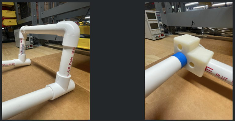
We went through an extensive design and redesign process for the joint shown to the left. It is used as both a 90 degree PVC connection and as a way to house the ball bearing which allows the legs to swing up and be stowed.
To the right is a deceptively simple component used for the swivel wheels. To prevent the wheels from locking up sideways, we worked at setting the swivels at an angle like a Rip Stick board. To do that, we had to account for the outside angle of the wheelchair and the angle to hold the swivel at. To connect these two angles, several loft functions were used, and now while the design is solid, the part is very difficult to dimension. It is a key feature, and testing showed us how mobile the wheelchair has become.
FULL ASSEMBLY

PARTS LIST
3D MODEL PARTS (PARTS SHOWN IN THE MODEL)
PVC Pipe for Structure
3D Printed 90-Degree Joint (Houses Ball Bearing) (Mirrored)
3D Printed Connection for the Legs (Houses Ball Bearing)
Ball Bearings and Connecting Axles
45-Degree PVC Pipe Connector
Specialized Printed Angled Joint (Connects to Swivel Wheel)
REAL PARTS (PARTS NOT SHOWN IN THE MODEL)
Screws and Nuts for the Suspension and Angle Join
Rip Stick Swivel Wheels
Upper Bar (Additional Support)
Springs (Coil-Over Style Shock System)
Specialized Screws (Ball Bearings)
Towel (Padding and Strapping)
ASSEMBLY DRAWING

PROCEDURES AND PARAMETERS
TESTABLE PARAMETERS
Maneuverability, Function, and Compatibility. Current designs create issues in each of these fields, prototype must allow for better turning radius, freedom for the dog, easier usage, more effective support, and rehabilitation capabilities.
FINAL BUILD PROCEDURES
1. Gather all parts together.
2. Glue all PVC parts together to create a stronger permanent frame.
3. Drill holes for the suspension and bottom angle joint.
4. Put in screws with appropriate nuts for the position and stability.
5. Attach towel in conjunction with the dog and apply straps by sewing the towel around the pipe or using screws to hold it in place.
6. Let your dog go where it pleases once more.
MATERIALS UTILIZED

CONSTRUCTION PHOTOS
This day was focused on brainstorming and visualizing the design on the dog. Luna's measurements were taken.

RIGHT PICTURE: Cutting and laying out the layout of the supportive upper frame.
LEFT PICTURE: Cutting and printing 90-degree supports.
RIGHT PICTURE: Fixing the suspension insert to the frame, and testing the swivel motion.
LEFT PICTURE: A nearly fully assembled frame.

SUMMARY
Modifications made during the building process include adjusting spring heights, incorporating lateral support that braced the frame to add rigidity, and reprinting swivel wheel casing. Data testing included: testing the laying area for the dog, testing how the back bar weight affects the front shoulders, and testing how the weight on the support area affects the front shoulders. The design is solid enough to work on Luna, changes would need to be implemented if scaling the design up or down.